LS8397
Stepper Motor Controller (24 Pins)
View Datasheet
View Footprint on SnapEDA
Buy on Digi-Key

All of our Standard Products are RoHS Compliant
$6.68 – $7.31Price range: $6.68 through $7.31
Select Product and Package Type below:
LS8397
Description
Full The LS8397 Stepper Motor Controller generates four-phase drive signal outputs for controlling two-phase Bipolar and four-phase Unipolar motors. The outputs are used to drive two H-bridges for the two motor windings in the Bipolar motor or the four driver transistors for the two center-tapped windings in the Unipolar motor. The motor can be driven in full step mode either in normal drive (two-phase-on) or wave drive (one-phase-on) and half step mode. The LS8397 provides two inhibit outputs which are used to control the driver stages of each of the motor phases. The circuit uses STEP, FRD/REV and HALF/FULL inputs in a translator to generate controls for the output stages.
A dual PWM chopper circuit using an on-chip oscillator, latches and voltage comparators is used to regulate the current in the motor windings. For each pair of phase driver outputs (PHA, PHB, and PHC, PHD) each pulse of the common internal oscillator sets the latch and enables the output. If the current in the motor winding causes the voltage across a sense resistor to exceed the reference voltage, VREFs, at the comparator inputs, the latch is reset disabling the output until the next oscillator pulse.
Input for a separate reference voltage VREFh is also provided for reducing holding torque when the motor is not turning. When holding torque mode is enabled with a resistor-capacitor pair connected to the RC Pin, the sense comparator input reference switches between VREFs and VREFh depending on whether the motor is turning or not. The separate sense reference voltages allow for conserving power when the motor is not turning. Holding torque mode can be disabled by connecting the RC Pin to VSS.
In the half-step stepping sequence, the phase drives alternate between one-phase-on and two-phase-on in successive steps at full power thus generating substantial ripple on the output torque. An input, CT_EN is provided for selecting an operational mode in which the torque ripple is corrected. In this mode the sense input reference voltage is switched to 100% and 70.7% of the applied voltages at the VREFs and VREFh inputs in successive one-phase-on and two-phase-on conditions, respectively. The CONTROL input determines whether the chopper acts on the phase driver outputs or the inhibit outputs. When the phase lines are chopped, the non-active phase line of each pair (PHA, PHB or PHC, PHD) is activated rather than deactivating the active line to reduce dissipation in the load sensing resistor Rs. If PHA is high and PHB is low, current flows through Q1, motor winding, Q4 and sense resistor Rs. When chopping occurs, PHB is brought high and circulating current flows through Q1 and D3 and not through Rs resulting in less power dissipation in Rs. Current decay is slow using this method. When the Control input is brought low, chopping occurs by bringing INH1 low. In this case circulating current flows through D2, motor winding and D3 and through the power supply to ground causing the current to decay rapidly. For Unipolar motors, only inhibit chopping is used. When INH1 is brought low the current flowing in either half of the center tapped motor winding recirculates through the diode across it.
Features:
• Low cost, low current, pin-compatible replacement for LS8297.
• L297 operating modes with added functions:
Selectable Torque Ripple Compensation MODE
Selectable Holding Torque MODE
• Other features same as LS8297
Additional information
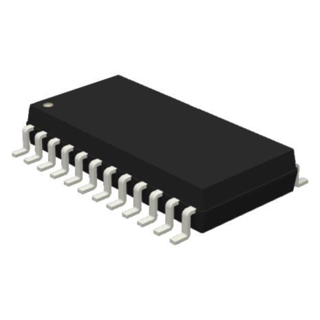
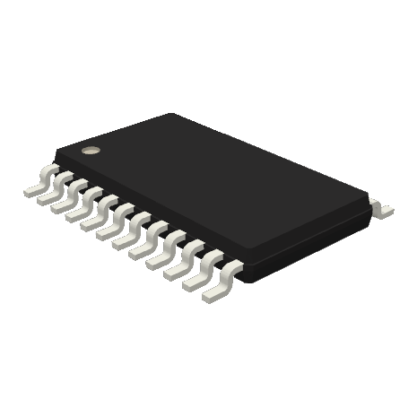
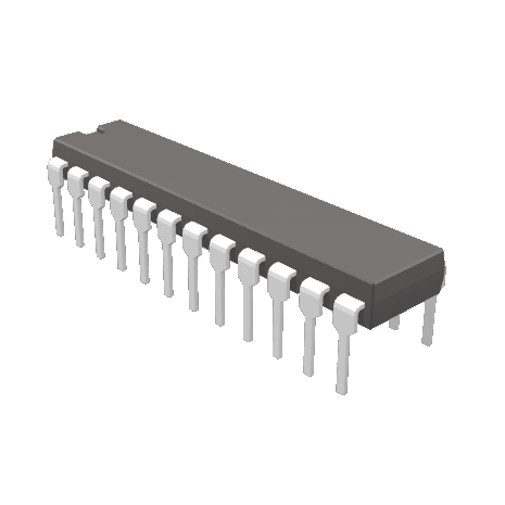
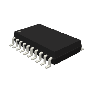
| Product | LS8397-S (24-Pin SOIC), LS8397-TS (24-Pin TSSOP), LS8397 (24-Pin DIP) |
|---|
Only logged in customers who have purchased this product may leave a review.
Similar Products:
-

LS8292, LS8293
$7.96 – $9.49Price range: $7.96 through $9.49 Select options This product has multiple variants. The options may be chosen on the product page -

LS8297
$5.36 – $6.40Price range: $5.36 through $6.40 Select options This product has multiple variants. The options may be chosen on the product page -

LS7290
$4.03 – $4.39Price range: $4.03 through $4.39 Select options This product has multiple variants. The options may be chosen on the product page

Reviews
There are no reviews yet.